Finally, a simple and reliable primary power solution.
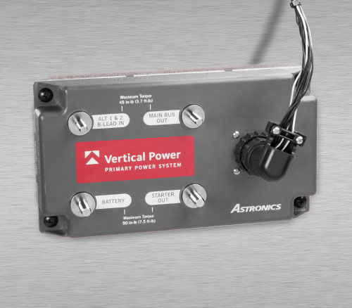
The Vertical Power Primary Power System (PPS) is an entirely new approach to the master, starter, and charging circuit on your experimental aircraft or LSA. It combines the functions of multiple high-current, electro-mechanical components into a single, solid-state device that installs in minutes with plug-and-play simplicity. Plus, the high-reliability of the PPS means you won't find yourself stranded on a deserted landing strip without the power to start your plane.
The PPS is Here!
We are pleased to announce the official launch of the Vertical Power Primary Power System (PPS) for experimental and Light-Sport aircraft.
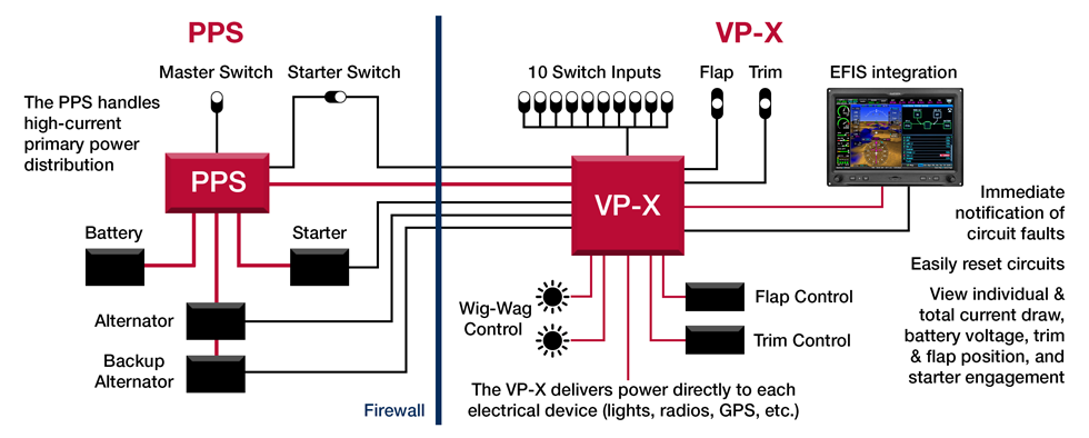
The PPS is a new power distribution component that handles your aircraft's high-current power. It controls the flow of power from the battery to the starter and supplies power to the Vertical Power VP-X (or a traditional bus) for your electrical system loads. The PPS also supports the charging circuit by completing the B-lead connection to the alternator (a basic system diagram is provided below).
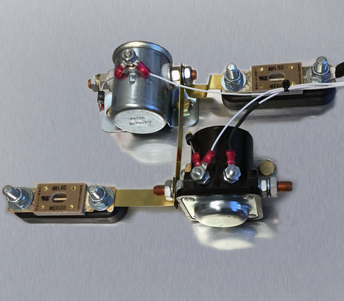
The Old Way
With the old way, you need to figure out which components are required for your electrical system, work out how they all fit together, and then build the system from scratch.
The New Way - PPS
With the new way, you buy one item, the PPS, and make the connections as labeled. That's it. No research. No fabrication. No guesswork.
There Is No Comparison
Until now, your only primary power choice was the "old way", a combination of electro-mechanical components that haven't significantly changed in half a century.
Now you have a choice...the PPS.
The PPS is a carefully-engineered and highly-qualified device that eliminates the need for you to engineer and manufacture your own primary power circuit. This not only puts an end to common errors in homemade circuits, but the solid-state construction of the PPS proivdes extremely high reliability when compared to the failure-prone solenoids, relays and contactors used in traditional circuits. In addition, the plug-and-play design of the PPS installs in minutes, saving you valuable time and allowing you to fly that much sooner.
The Primary Power System Diagram
The PPS, shown on the left side of this diagram, can be installed or retrofitted on an experimental aircraft equipped with the VP-X Electronic Circuit Breaker System or a traditional electrical bus. Visit the Vertical Power System page for more information.
The only solid-state electrical system designed for experimental and light-sport aircraft.
There is no comparison. Vertical Power is the only solid-state electrical system designed specifically for use on experimental and light-sport aircraft. Whether you use the PPS or the VP-X individually, or both together for an end-to-end system, you will be using the finest, most reliable electrical system available today.
The PPS Benefits
Whether you are an experimental aircraft builder or an LSA manufacturer, the new PPS provides many unique and important benefits. High reliability and easy installation are just the start. Take a look at the lists below to see why the PPS is truly easier, safer and better than traditional components.
Easier
Speeds installation – easily mount one box instead of 5 or more individual devices.
Saves space – smaller than the old-style individual components mounted together on the firewall.
Clearly labeled for quick connection to electrical system.
Safer
Reduces exposure to components at battery voltage.
Eliminates hazardous and costly wiring mistakes.
Highly engineered and proven design – no need to solve the challenging puzzle of what components you need and how they should be connected.
Low static power draw of 1 mA – won't drain your battery if you forget to turn off your master switch.
Integrates perfectly with the Vertical Power VP-X system for a comprehensive solid-state electrical solution.
Specifications
Specifications for the Primary Power System are shown below. To get full details on the PPS, please visit our documents page and download the PPS manual.
General
Transient protection on all connections
The PPS is compatible with systems using a backup alternator in parallel with the primary alternator. The PPS is not compatible with two-bus systems.
Circuit Ratings
Main Bus Output
80 A maximum continuous
Starter Output
300 A maximum continuous
1200 A maximum intermittent
Alternator Input
80 A maximum continuous
Analog Current Monitor Outputs
Common-mode reference of 7.5 VDC
Scale: 1 mV/Amp
Short circuit protected
Environmental / Physical
Component Temperature Range: −40°C to +85°C
Storage Temperature Range: −55°C to +100°C
Weight: 1.6 lb (0.72 kg)
Operating Voltage: 8 – 36 VDC
Low quiescent power: less than 1 mA at 14 VDC and 28 VDC
Maximum power
320 mA at 14 VDC
140 mA at 28 VDC
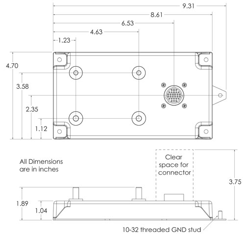
PPS Dimensions
We use cookies and similar technologies to improve your experience on our website.
Read our Privacy Policy.